Grimston E46 bench drill – “major service” part 2

Next… dismantle the drilling head sufficiently that I’d be able to lift it onto the workbench.  The quill and lifting gear came out without too much difficulty:


but separating the gearbox from the motor casting was more of a struggle.  Stanley-knife blades make very good wedge-shims!

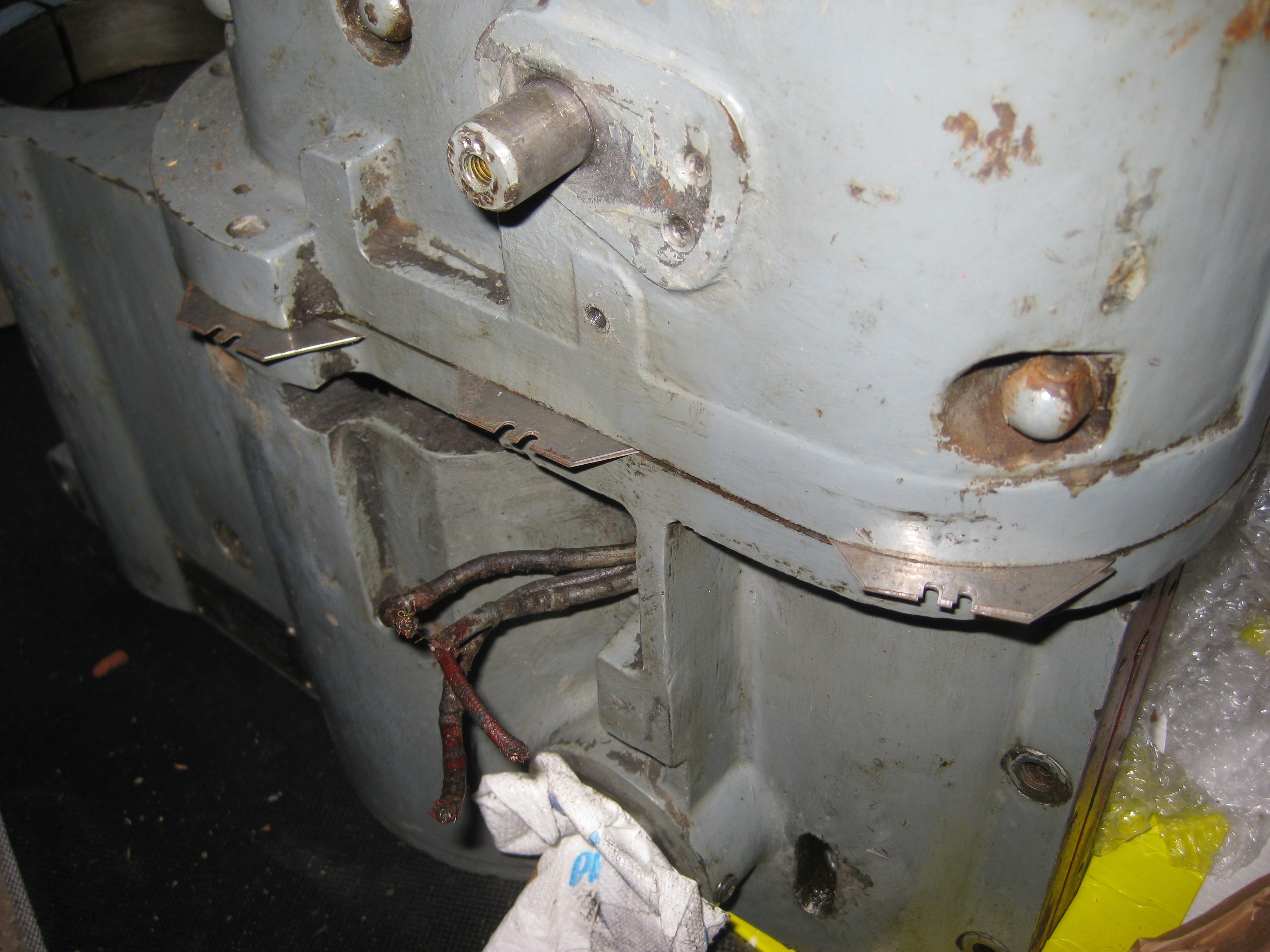
After a lot of wedging and re-shimming and wedging some more, the gearbox could be lifted away, but taking the motor armature with it.  And so was revealed…


Mmm, niiice!  Plenty of de-greasing required there.  The gearbox and motor armature were now liftable onto the bench:


The motor lower cover cleaned up nicely – I can recommend WD40 de-greasing spray.


And finally I was able to lift the main casting onto the bench and get to work on it.  The head lifting gear was caked in old grease, but underneath showed no signs of wear.  Gently tapping out the worm-gear shaft with a drift took some time, but I didn’t want to risk cracking the cast-in mounting bracket:


Using only iso-propyl alcohol to avoid any possibility of damaging the motor-winding insulation, the black grime gradually receded.  I wasn’t filled with confidence by the state of the insulation on the motor tails (some kind of resin-impregnated fabric with rather crumbly black stuff beneath), so I sleeved them with some not-very-1950s heatshrink tube, and tidied up the bare ends with crimped bootlace ferrules:


I’d ordered a suitably robust bench from Tecnik Engineering in Hereford (nice people, good product!), and now was the time to assemble it.  I added a couple of 4×2 cross-braces and a top made of MDF cannibalised from a defunct treadmill.  Then I temporarily reassembled the drilling head on it, connected up the motor to the Control Techniques VFD, and bravely went for a cup of coffee and just one more read-through of the VFD user-manual before gingerly turning it on…


And it runs!  For the first time in how many years, the motor gradually wound up to 2850RPM (I’d programmed the VFD for 120V and 1A, treating it gently).  It was quite noisy, so I’m now thinking that disassembling and cleaning the gearbox has to be next on the list.


One point worth mentioning here – “re-forming” of VFD/mains-inverter capacitors.  All manufacturers of VFDs recommend a “run-in” procedure for any unit that hasn’t been used for more than a year, and having bought this unit off Ebay I had no idea when it had last been powered up.  The methods and details vary, but in essence it means charging up the unit’s internal high-voltage capacitors in a controlled fashion with gradually increasing voltage to “re-form” their dielectric insulation layer.  Having access to a Variac (variable mains transformer) at work, I chose to start my VFD off running from about 60V AC, leaving it at that for a couple of hours, then increasing the voltage in 30V-ish increments every hour or so through the day.  By close of play it was up to about 260V and no magic smoke had escaped.  This seems to me a safer way than running it from the full 240V mains voltage with a current-limiting resistor, but I guess if you don’t know someone with a Variac this may be the only practical option.

Grimston E46 bench drill – “major service”

I’ve always wanted a pillar drill, and having previously had the privilege of using a Meddings GHF, a geared head model definitely appealed. Then I spotted this on Ebay…

The only info I could find about it online was this website – thank you to Tony Griffiths.  No definite manufacture date, but it’s probably late-1940s/early-1950s – looking OK for 65+ years!
The bench model EB46 is quite compact, less than 1 metre high, but weighs in at over 150kg.  Grimston really built them to last!  It has a 4-speed gearbox (2 selector levers on the left-hand side of the head), and a 0.9HP 3-phase motor which is integral to the lower half of the head – no simple “replace it with a single-phase” job.  But no worries, there are plenty of second-hand 3-phase inverters available under £100, let’s have fun with 415V.

This is how it looked when I got it home:


And having dismantled it into (barely-)manageable pieces:

 IMG_3365

IMG_3368  IMG_3400_cropped

I’ve started to clean it up, and everything seems to be in pretty good order.  It had been standing idle (not even wired up) in a farmer’s workshop for a number of years, and was covered in a protective layer of dust-hardened grease.  As I took it apart, I was surprised and delighted to find that none of the bolts had seized, and several patches of surface rust turned out to be just rust-tinged grease with clean iron or paint underneath.  I also checked the resistance of the three motor connections – the same ~24Ω between each pair, and >20MΩ from any of them to chassis.

My current plan is not to go for a full strip-down and restoration, but just to treat it to a 70-year “major service” and get it working again.  Clean out the dirt/oil/grease from the motor and other exposed working parts, but keep the gearbox intact, as that’s essentially a sealed unit and seems to turn quite smoothly.  Then wire it up to a Variable-Frequency Drive module (a 550W Control Techniques’ Commander SK, £75 from Harrogate Automation Controls) and gently run up the motor.  A VFD will allow you to run a motor at lower voltage than full mains, with limited current, and even “soft-start” it by ramping the frequency up over a few seconds – this poses much less risk of damaging the motor than simply connecting it to a 3-phase mains outlet and keeping your fingers crossed.

IMG_3404_cropped

Mini pillar-drill and cross-table

I recently bought a table-top mini pillar drill, sold in UK by AIM Tools as Katsu 100080, and added a small cross-table (Katsu 402188 from AIM Tools, AKP-201 on Alibaba) to create a precision drilling setup.  Total cost only £144, and I’m very pleased with the result:

Drill1

The drill has no noticeable run-out – in contrast to a full-size pillar-drill, the motor moves up and down with the quill, and there is no extending spline (which seems to be the problem with cheap pillar-drills I’ve used), though this does limit the rise/fall (and hence maximum drilling depth) to only 25mm.  The chuck only holds drills up to 6.5mm, so precision jobs is what it’s made for!  It’s powered by a sewing-machine motor rated at only 100W, but it did OK drilling 3mm holes in cast iron, you just have to take your time (again, precision jobs…).

The base of the mini-drill is cast iron, and I was expecting problems in drilling and tapping the four fixing holes for the cross-table, but no – didn’t encounter any hard spots, and it tapped more easily than aluminium.  I didn’t apply any lubricant to the tap, and the waste (quite fine iron filings) simply dropped out of the hole rather than clogging it.

DrillBase

The action of the cross-table is superb – backlash is minimal, but the gib screws are not insanely tight (in marked contrast to a £50 cross-vice I’ve used, which needed constant tweaking of the gib screws).  Weighing in at 11kg, it will definitely keep the drill steady!

Since the tapped holes in the drill base had gone so well, I drilled and tapped some M4 holes into the rear face of the cross-table (same story, easy peasy!) to attach a flat plate, creating a “lip” along the rear edge of the table for easy alignment of rectangular work-pieces:

TableRear

Another possible enhancement for the future is to add a taller drill column  – as supplied, it’s only just high enough to give useable clearance between the chuck and the table.  It appears to be made from any-old steel tube, turned to 32.5mm diameter.  I’ll probably use solid 35mm round bar – luckily I know a man with a lathe…

Detecting car keyfob jamming using a Raspberry Pi and a DVB-T dongle

The use of RF jammers or blockers by criminals to break into cars is spreading – this BBC News report is from December 2016, and this from May 2017.  How can you protect yourself?  This Hackaday post describes a simple “yes/no” receiver to detect jamming on the car-keyfob frequency.  Better than nothing, but it doesn’t tell you whether you’re right in the crims’ target zone, or half a mile away.

I had been messing around with a cheap RTL-2832 DVB-T dongle, and it seemed like it should be quite straightforward to use it as a direction-finding/homing receiver to give a “warmer/colder” indication and work out exactly where a jammer was being used.  As it turned out, the software-radio bit was quite easy – the tricky part was making Linux generate simple beep-tones to indicate the signal-strength!  (anyone else fondly remember the ZX Spectrum Basic BEEP command?)

Low_cropped

Jammer-Detect running on a laptop – the bar-graph extends across the screen and changes colour to indicate RSSI on every “sample”, while beep-tones about play once a second indicating the maximum signal-strength received in the last 32 samples.

The main part of the code is written in Python 3, with the RF-power calculation implemented in C for efficiency.  It can be run on a laptop, but the real fun starts when you install it on a Raspberry Pi that fits in your pocket – a single earphone feeds you audio tones that indicate “warmer / colder”, and you can then walk or drive around an area to track down the source of a jamming signal.

Jammer_detection_setup

Pocket-size jammer-detection kit: Raspberry Pi 2 in plastic case, right-angle micro-USB cable to rechargeable power-pack, small DVB-T dongle (larger alternative in background), antenna and earphones.

How to build it

Create a Raspbian bootable micro-SD card by following the instructions here.  Raspbian Lite will boot faster than the “With Desktop” version, so I used that.

Put the micro-SD card into the Pi, and connect a monitor, USB keyboard, network cable and power-supply.  When the Pi finishes booting and shows a “raspberrypi login:” prompt, log in as “pi”, “raspberry” and execute the following commands to install required packages and download the source-code from Github:

mkdir jamdet
cd jamdet
sudo apt install git automake shtool libtool libusb-1.0 python3 python3-pip libasound-dev
wget http://www.portaudio.com/archives/pa_stable_v190600_20161030.tgz
sudo pip3 install --upgrade pip wheel setuptools
git clone https://github.com/mikeh69/librtlsdr
git clone https://github.com/mikeh69/pyrtlsdr
git clone https://github.com/mikeh69/JammerDetect

Build and install PortAudio and its Python bindings:

tar -xvf pa_stable_v190600_20161030.tgz
cd portaudio
./configure
make && sudo make install && sudo ldconfig
sudo pip3 install pyaudio

At this point you can disconnect the Pi from the Internet if you prefer to.

Now build and install the RTL-SDR library and Python bindings for it:

cd librtlsdr
autoreconf -i 
./configure
sudo rm /usr/lib/librtlsdr.*
make && sudo make install && sudo ldconfig 
cd ../pyrtlsdr 
sudo python3 setup.py install 
cd ..

Finally, install a Udev rule and driver-blacklist to allow user-mode access to the DVB-T dongle:

cd JammerDetect
sudo cp 88-dvb-t.rules /etc/udev/rules.d/
sudo cp blacklist-dvb-t.conf /etc/modprobe.d/
sudo reboot

(and log in again as pi – raspberry).  The Udev rules file also includes an “unplug” rule that tells the Pi to shut down in an orderly fashion if the DVB-T dongle is unplugged – a cleaner solution than just pulling the power!

Now try out the program.  The first time it runs, it will take a minute or so to generate the audio-tone data and save it to a file.  On subsequent runs, the tone-data will be loaded from the file, which is much quicker.  Plug in your DVB-T dongle, and type:

sudo amixer cset numid=1 100%

to set the audio-output volume to 100%, then:

cd jamdet/JammerDetect/src
python3 jammer_detect_main.py

(Press Ctrl – C to break out of the program).

To make the program run automatically when the Pi boots, do:

crontab -e

(which opens the “cron table” file in an editor), and to the end of the file add this line:

@reboot /usr/bin/python3 /home/pi/jamdet/JammerDetect/src/jammer_detect_no_ui.py

(Press Ctrl-X, Y to save and exit from the Nano editor).  This runs a version of the program that has no graphical display, just the audio tones, because an automatically-run program has no console to send graphics to.

sudo reboot

and listen to the earphone…

The centre-frequency of the band is currently hard-coded to 433.92MHz (the European car-keyfob band), but the Python script (jammer_detect_main.py or jammer_detect_no_ui.py) can simply be edited to change this to any frequency that the DVB-T dongle is able to tune to – see this page for tuning ranges of various dongles.

The antenna doesn’t have to be particularly “good”, or well-matched to the frequency of interest – if a jammer is putting out enough power to be effective, your receiver won’t need great sensitivity to pick it up!

Next bit of work might be to improve the large-area survey (driving around a city) – go back to running on a laptop, add a USB GPS puck and keep a log of signal-strength against lat/long, then generate a “heat-map” KML file to display on Google Earth…


Acknowledgements:  Thank you to Steve Markgraf for LibRtlSdr, and to “Roger” for the Python bindings.  I’m standing on the shoulders of giants…


I mentioned earlier the trouble I had generating simple audio tones.  The difficulty was in preventing unpleasant clicks at the start and end of a “beep”.  It turned out to be necessary to fade IN, as well as fade out, each tone.  audio_tones.py generates sets of samples for PortAudio to create beeps at semitone intervals – it’s completely self-contained and can be used in other projects.

Clansman/Cougar cable NSN 5995-99-653-0491

This cable is available for £7-10 from a couple of EBay sellers (search for “Clansman H-39 handset wiring” or “Clansman cord assembly”) , and could be useful for connecting up Racal Clansman or Cougar kit.

It ends in an Amphenol plug, part no. AB06-6221-10-07PF-01.  Its pinout is:
A (microphone) – Red wire
B (mic return) – Green wire
C (10V power) – not connected
D (audio/data) – Orange wire
E (ground) – Blue wire (joined to braid around Red wire)
F (PTT, channel/crypto data) – Black wire
G (squelch/CTS) – not connected

As you’d expect for a mil-spec item, it’s very well made, including a nylon strain-relief cord tied off to a steel toggle-pin inside the connector.  But… there is a white wire, which is terminated with the same type of crimp as the other coloured wires, but at the plug end of the cable it’s trimmed off and not connected to anything! What a massive D’OH!

It’s very fiddly, but I was able to open up the plug and solder a new piece of wire from pin C to the end of the white wire.  (You need to use large pliers/plumbing grips and a rag to avoid scratching the paint too badly, as there is locking compound applied to the threads.)  Getting the connector reassembled with the toggle-pin in the right place is fun (not).  With DC power connected through, it becomes a lot more useful!

Alternatively, Ebay seller MartinJarvisMultiband has two versions of the plug for sale (message him if none currently listed), and Lapp cable type 0034307 LIYCY from Ebay seller 123dls-industrial works quite well with it (though doesn’t have the nylon strian-relief cord).

EVidMag – an open-source Electronic Video Magnifier for people with impaired vision

I’m doing some work to develop a low-cost desktop Electronic Video Magnifier system to allow people with impaired vision to view hardcopy documents on a computer monitor, with functions to adjust brightness and contrast, change colour scheme, zoom in and out etc.  Commercial desktop EVMs are available, but cost in the thousands of pounds/dollars.  This system will use an £80 USB document camera, a user’s existing PC and monitor (or e.g. a Raspberry Pi and a TV) and free open-source software.

Permanent page will be maintained at mikeh69.wordpress.com/evidmag/

Would be useful to know if this is of interest to anyone…